Interfacing 7 Segment Display with Raspberry Pi Circuit Connection👇👇👇👇
Follow @circuit_digest
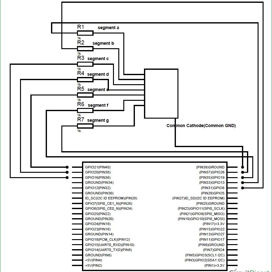
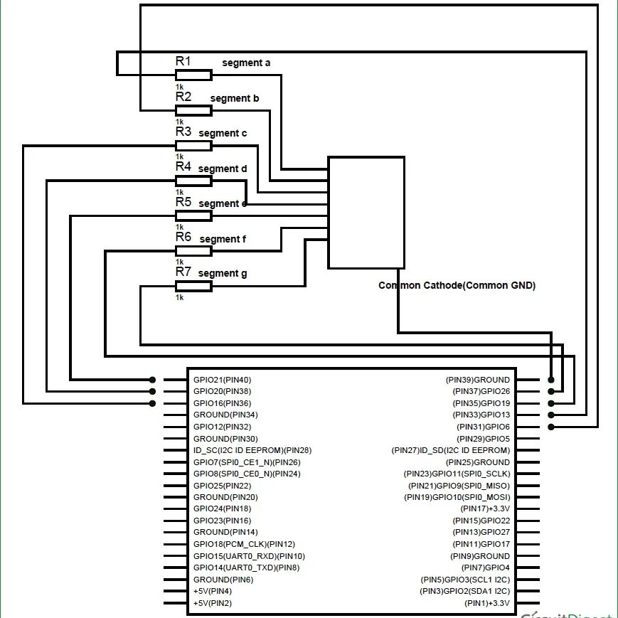
The connections, which are done for Interfacing 7 segment display to Raspberry Pi, are given below. We have used Common Cathode 7 Segment here:
PIN1 or e —————— GPIO21
PIN2 or d —————— GPIO20
PIN4 or c —————— GPIO16
PIN5 or h or DP ———- GPIO 12 //not compulsory as we are not using decimal point
PIN6 or b ——————GPIO6
PIN7 or a ——————GPIO13
PIN9 or f —————— GPIO19
PIN10 or g —————- GPIO26
PIN3 or PIN8 ————-connected to Ground
So we will be using 8 GPIO pins of PI as an 8bit PORT. In here GPIO13 is being LSB (Least Significant Bit) and GPIO 12 being MSB (Most Significant Bit).
Now, if we want to display Number “1”, we need to power segments B and C. To power segment B and C, we need to power GPIO6 and GPIO16. So the byte for ‘PORT’ function will be 0b00000110 and the hex value of ‘PORT’ will be 0x06. With both the pins high we get “1” on display.
#7segmentdisplay
#raspberrypi
#interfacing #raspberrypitutorial #raspberrypi4 #raspberrypiprojects #circuit #circuits #connection #schematic #schematics #electronicsprojects #electronicsmaker #electronicslovers #electronicsengineering


コメント