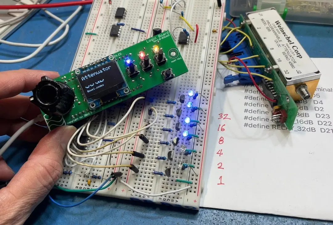
Remember…. ASSUMPTION is the mother of all fuck-ups. And that’s why we test it first on the breadboard… I wrongly assumed that the inductor coils inside this attenuator doesn’t care about polarity. And that the COM terminal just means it’s the common terminal to all the relays, i.e. connected together. Well, I’m partially correct.
It’s polarized. The COM terminal must also be the GND connection. It’s common negative, not common positive. So the previous transistor switching scheme I dreamt up won’t work with this attenuator when you want to trigger multiple relays independently.
Anyways, the UDN2982 part on this attenuator is obsolete, but found a likely replacement that I can use on my own PCB board. It’s a TBD62183AFNG,EL part, and commonly available for about $1.25. SSOP-18 Package. So I think that’s what I’ll use instead.
For now, GPIO control is working as shown in video demo, we convert the decimal number to binary equivalent and enable/disable the appropriate relays. For now, the relays are represented by these LEDs.
Stay tuned…
If you like electronics content like this, please LIKE and FOLLOW. Thanks!
#schematic #esp32 #digitallogic #transistors #relays #resistor #diodes #electronics #electronicsengineering #learnelectronics #fluke #current #voltage #switching #gpio #arduino #breadboard


コメント